1. Introduction
The concept of VLC (Visible Light Communication) has an ongoing increase in popularity as more alternatives for conventional telecommunication protocols are developed or improved. Main reason for this fact is that the spectrum of the conventional RF (Radio-Frequency) based systems simply cannot accommodate the increase in current demand and predicted high data rate services requests. Therefore, an increased number of researchers are continuously exploring different types of transmitters and receivers, as well as different modulation techniques.
Beia Consult International also takes part in this effort through its Research and Development department with the Hybrid VLC/IR-RF (Visual Light Communication/InfraRed-Radio-Frequency) research project which has started in 2017, project supported in part by UEFISCDI Romania under grant no. 97/2017.
In this paper is presented an iteration of the VLC system based on the ARM Cortex-A53 processor which can also be integrated with the 230VAC, 50Hz power grid. This system presents the capability to provide to the users a very secured and easy way of data transfer. The communication channel can only be penetrated from inside the building / perimeter in which it was installed, by overlapping a foreign optical receiver.
The paper is structured as follows: Section 2 presents the current State-of-Art in this field. Section 3 makes a full description of the proposed system and of the way it works, whilst Section 4 presents the physical experimental results when integrating the proposed system in an SME (Small and Medium-sized Enterprise) office. Section 5 illustrates the conclusions of this research and future work and development which will be included in the Hybrid VLC IR/RF project.
2. Related Work
The idea of utilizing at once illumination and data communication using the same physical carrier was firstly proposed in 2003 (Komine and Nakagawa, 2003). Nakagawa Laboratory perfumed several novel studies in this research area during the years (Komine et al., 2004) (Tanaka et al., 2003).
A thorough presentation is made (Khan, 2017) on the whole concept of VLC communication including applications, architecture type, standardization, and research challenges. The authors start with the disadvantages of RF communications and then proceed to describe the main features of the VLC along with its history. After that, the main applications of VLC, such as Li-Fi, Vehicle-to-Vehicle communication, Visible light ID systems, etc. are detailed. In the Architecture section, authors mention that generally, VLC systems (with transmitters and receivers) consist of three common layers: physical layer, MAC layer and application layer. Each of these layers is particularly described. Multiple types of transmitters and receivers are also compared. The last part of the paper includes details about the different modulation techniques that can be applied with the concept of VLC: On–Off Keying (the modulation used in this research paper), Pulse Modulation, Color Shift Keying.
A vehicular visible light communication system is proposed (Yoo et al., 2015), in which LED (Light-Emitting Diode) headlamps are used. The authors use the basic transmitter-receiver concept and an inverse 4-PPM modulation scheme. The transmitter consists of a modulator, a LED driver and the actual LED headlamp, while the receiver consists of a photodetector, amplifiers and filters, an analog-to-digital converter, a demodulator and a data output. Experiments were conducted in broad daylight, on distances varying from 5 to 40 meters (with measurements conducted every 5 meters). The data packet consisted of 4 bytes (data – 1 byte, sync – 2 bytes, header – 1 byte, data – 1 byte, sync – byte) and the frequency was set at 20 kHz. Therefore, at 20 meters the authors claim and prove a 10Kbps data rate.
One of the main goals in current VLC development is to achieve high data rates (Yonus and Elmirghani, 2017). For that WDM (Wavelength Division Multiplexing) is used along with red, yellow, green and blue laser diodes (such as transmitters) and an IMDR (Imaging Diversity Receiver) as a receiver. For the actual implementation, the authors provide simulations based on an 8 x 4 x 3 meters room with no doors or windows. Using MATLAB simulations, it is demonstrated that the system can achieve an aggregate data rate of 10 Gb/s over the entire proposed room with a bit error rate (BER) of 10-6.
VLC can also be used in indoor hospital use cases (Ding et al., 2015). Considering the increase of E-HEALTH system, the authors propose a hybrid broadband power-line and a VLC system with orthogonal frequency division multiplexing modulation. The system is meant to replace the conventional wireless communication systems in hospitals. This hybrid implementation consists of a PLC Modulator, a PLC to VLC conversion module, a demodulator and a receiver. Basically, data is sent to the PLC Modem and then through the power-line. Power-line LEDs then output the data through VLC. A physical demonstration is described: the system can provide a data rate of around 48Mbps within the bandwidth of 8MHz located from 2MHz to 10MHz (over 5 meters).
An underwater VLC system that can represent an interest in both military and industry sectors was also developed (Wang et al.). The half-power angle of LED is narrowed to increase the optical intensity of the transmitted light. For the receiver, it is used a SPAD (Single-Photon Avalanche Diode) to improve the detection sensitivity. The communication channel parameters are obtained with the help of the Monte Carlo numerical simulation method. Also, in the article are proposed a SPAD detection algorithm and an optimal detection threshold of the underwater VLC system. Experiments are made for two types of water, pure seawater, and clean ocean water. Simulations that are made in the article show a transmission distance of up to 500 meters in the pure seawater.
2011 was the year in which the Institute of Electrical and Electronics Engineers (IEEE) succeeded to release the 802.15.7-2011 standard for VLC communications (Sklavos et al., 2013).
3. Proposed VLC communication system
The general architecture of the system is presented in Figure 1.
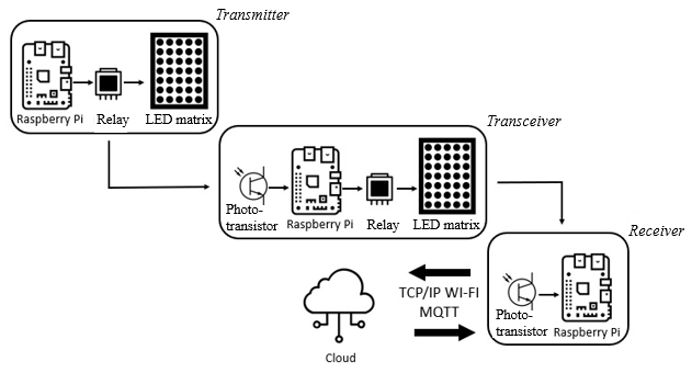
Figure 1. General architecture of the system
As it was stated before, the proposed system is part of the Hybrid VLC/IR-RF project. An earlier version of this approach was described (Suciu and Scheianu, 2019), where the architecture is based on an Arduino development board. The main reason for switching to a Raspberry Pi minicomputer is its ‘complete system’ status and its communication capabilities (integrated Wi-Fi and BLE). Although this approach is based on light communication, it was considered that full integration with existing communication protocols is also needed. Therefore, in this particular case, the Raspberry Pi extends the Arduino GPIO advantages with powerful, easy-to-use and easy-to-configure communication which can be exploited to their full potential.
The system uses area-to-area communication and On-Off modulation. The current development stage included the integration of the system in the common power grid of a building.
The architecture consists of a transmitter sending information to a receiver through visible light. A transceiver can be interposed between these units to extend the range (for example, in another room). All of the units are based on the Raspberry Pi 3 Model B+ minicomputer.
The transmitter includes the processing unit various sensors (temperature, light, dust, sound, movement), an electromechanical relay and a LED matrix. The receptor includes the processing unit and a light detecting component (photo-transistor). The transceiver includes the components from both the transmitter and the receiver (except the sensors) so it can collect incoming signals and then forward them. A detailed architecture of the transmitter can be observed in Figure 2.
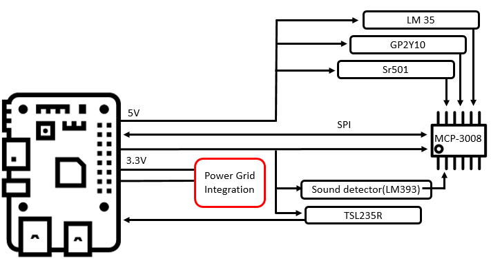
Figure 2. Architecture of the transmitter
The transmitter uses an MCP-3008 analog-to-digital converter to acquire data from the sensor. Although some of the sensors are, in fact, digital and would not require a connection through the MCP-3008, it was preferred to detect the actual values of HIGH and LOW voltage to a more facile integration and processing of the data. Also, the SPI (Serial Peripheral Interface) protocol is used between the Rasberry Pi and the converter so that the number of sensors can be easily increased.
For each sensor, the output data is transformed into a binary number. The binary values obtained from the sensors in each reading are concatenated in order to obtain a binary string. Using the 3.3V logic, a HIGH signal is an output for each 1 in the string, while each 0 corresponds to the LOW value. The previous implementation of the system included a LED connection that could On-Off modulate the information. In the current implementation, the 3.3V interface is inputted into a signal conditioning circuit consisting of a NPN (Negative-Positive-Negative) transistor and an electromechanical relay, as it can be seen in Figure 3.
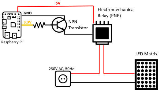
Figure 3. The Transmitter - LED Matrix connection
This configuration is needed as the relay (which can be observed in Figure 4) uses a PNP (Positive-Negative-Positive) transistor. The powerful LED matrix is powered via the relay only when the GND value is inputted into the relay. As the LOW value of the Raspberry Pi is different from the GND value a physical connection between the GND pin of the Raspberry Pi and the input pin of the relay is required. Controlling of this connection is realized with the NPN transistor.
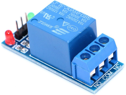
Figure 4. The electromechanical relay used
Additional details about the relay are presented. According to the device’s data-sheet, it is equipped with a single channel, requires a 5V supply voltage and a maximum 5V control voltage. The data-sheet also states that the device is based on an NPN transistor. This fact was practically demonstrated to be incorrect as the high-power circuit is switched on only when inputting a GND value. The maximum voltages allowed on the power side are 250VAC, 125VAC, 28VDC, 30VDC. The maximum current supported, according to the voltages, is 10A. It is provided with 3 terminals:
- COM - "common";
- NO - "normally open" - normally open;
- NC - "normally closed" - normally closed.
The diagrams in Figure 5 point out how the relay works.
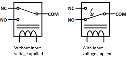
Figure 5. Working principle of the relay
An assembled version of the transmitter can be observed in Figure 6.
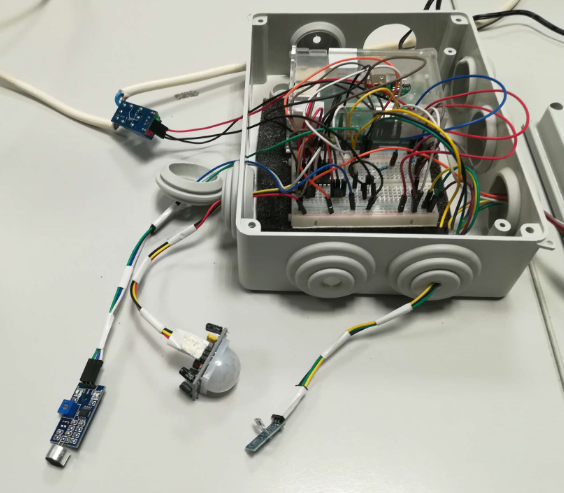
Figure 6. The assembled transmitter
The light, sound and movement sensors are visible, while the temperature sensor is placed inside the case and the dust sensor is placed on the case lid. Figure 7 shows the transmitter equipped with the powerful LED matrix.
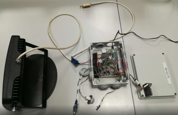
Figure 7. The transmitter equipped with the LED matrix
The particularities of the transmission device are as follows:
- Power: 70W;
- Voltage: 220-240V;
- Frequency: 50Hz;
- Power factor: >0.95;
- Temperature (colour): 6500K;
- Dispersion angle: 110°;
- Light flow: 5600Lm;
- Ra: >80;
- IP65 certification;
- Medium life expectancy: 25000 hours.
The receiver is expected to detect the incoming signal, decode it and also provide integration with existing protocols. The architecture of the receiver can be observed in Figure 8.
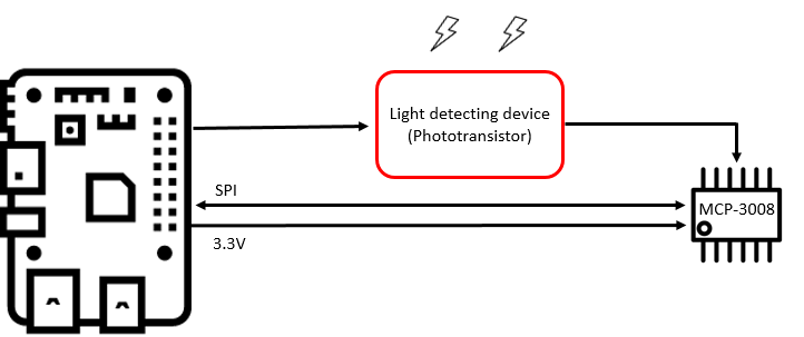
Figure 8. Architecture of a receiver
Early versions of the transmitter included the use of a wide spectrum of photo-transistors and different types of photo-diodes. The receiver is constantly measuring the ambient light level in order to detect any changes that might come from the transmitter. The same analog-to-digital converter is used. In terms of synchronization, both the transmitter and the receiver share the same wait time between each binary transition.
In terms of frequency, the whole system is bottlenecked by the electromechanical relay which has a minimum switching time of 10ms, which is insufficient for eliminating the flicker effect of the On-Off modulation (and therefore not perturbing human activities). Earlier implementations of the system achieved transfer rates up to 0.48Kb/s (with common LEDs and without any relay). In the present configuration, the electromechanical relay cannot physically commute faster. The ways of improving this flaw are presented in the Conclusion section of this paper.
As it was already stated, the transmitter can also forward data through the Internet-based, M2M, open-source protocol and MQTT.
In terms of software development, both the transmitter and the receiver are using programs written in Python 3 and configured to automatically start at the Raspberry Pi’s boot. Python 3 was considered the most suitable programming language in this case due to its high library count, prototype orientated nature and simplified syntax.
4. Experimental Results
In Figure 9, the working system can be observed. The transmitter can be observed at the bottom of the figure, while the receiver is red-circled.
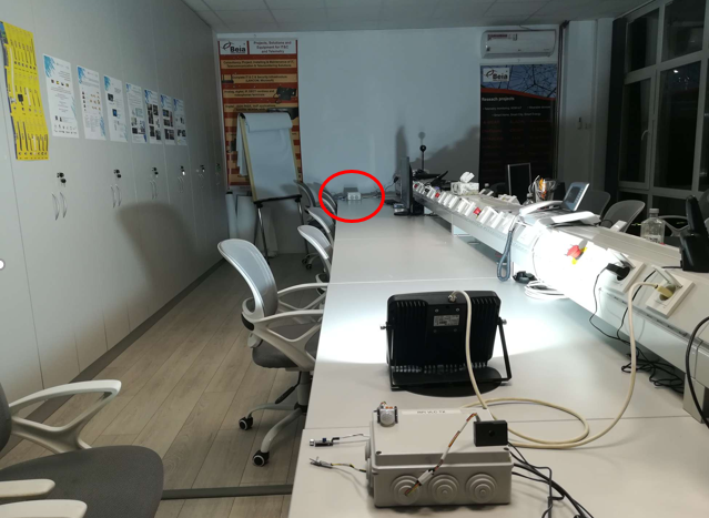
Figure 9. The VLC working system
In order to rigorously test the system’s performance, the following process was considered. The transmitter will send data both to the receiver (through VLC) and to an MQTT broker through MQTT (using Internet connection). The receiver will detect the data from the transmitter and will forward it via MQTT to the same broker, which will store the two sets of data into the same database. After that, using the online and open-source visualization tool, Grafana, the two sets of data will be displayed on the same graphs. Any inconsistency between the two graphical representations or any difference will mark if/when the VLC system did not perform as accordingly. The process flow can be observed in Figure 10.
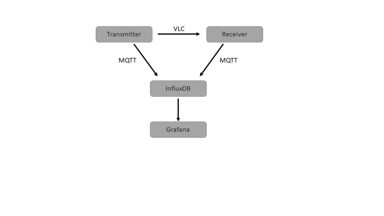
Figure 10. Testing process flow
Before the actual graphical testing, the message exchange through MQTT was monitored using MQTT-Spy software. In Figure 11, the message flow from both the Transmitter and Receiver can be observed.
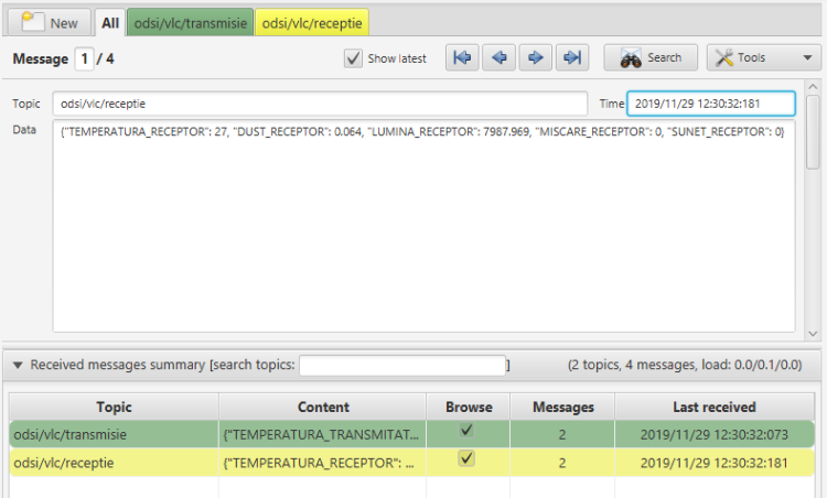
Figure 11. Message exchange in MQTT Spy
Figures 12-16 correspond to the graphical representation for the 5 different sensors. The yellow function corresponds to the directly sent data (transmitter), while the blue function corresponds to the data sent through VLC (receiver).
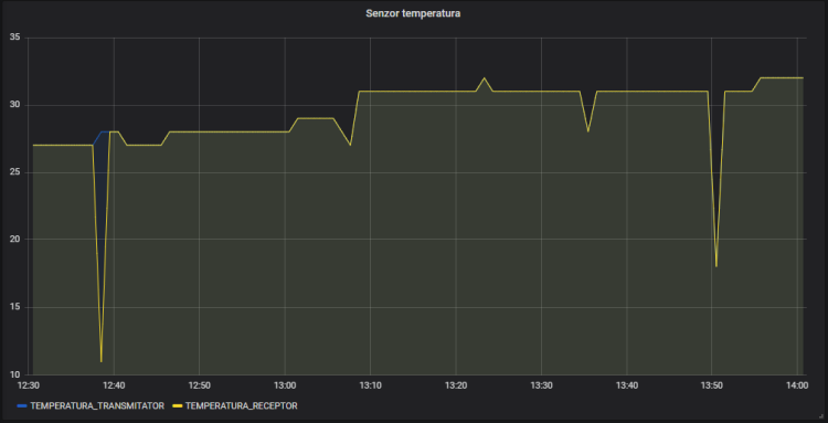
Figure 12. Temperature sensor
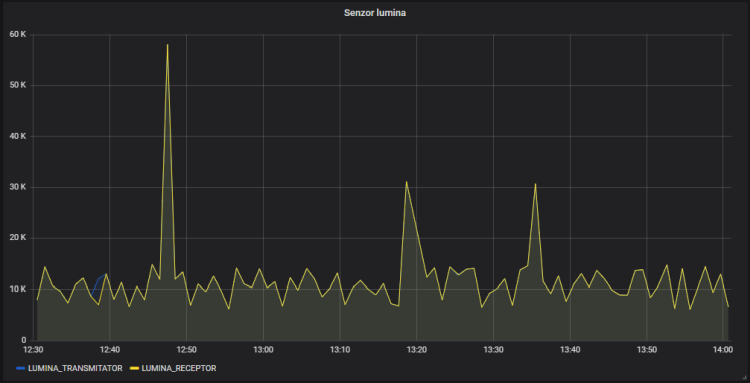
Figure 13. Light sensor
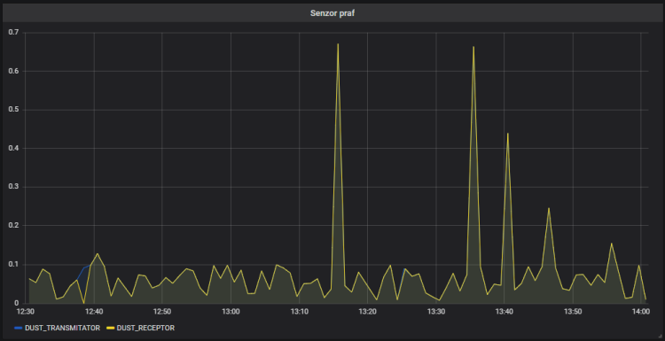
Figure 14. Dust sensor
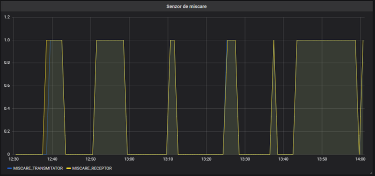
Figure 15. Movement sensor
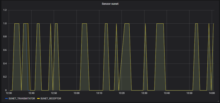
Figure 16. Sound sensor
As it can be observed, all of the 5 figures do share a moment when the yellow and blue functions do not perfectly match. It is determined that, for that particular dataset, the VLC transmitted binary string is completely unreliable. Additionally, in Figure 17, the delay between the datasets can be observed. On average, the VLC data arrives with a 10 to 20ms delay.
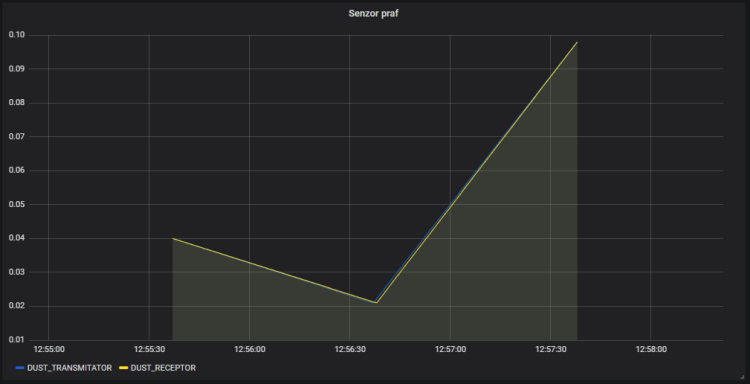
Figure 17. Delay between data
5. Conclusions
In this paper it was presented an improvement in the VLC concept. The old processing unit (Arduino Uno) was replaced with the ARM Cortex A53 based Raspberry Pi 3 Model B+. Also, the necessary modifications were made in order to integrate the system into the 230VAC, 50Hz power grid. A new validation method was also used, which included the integration of the MQTT protocol and the visualization platform Grafana. Overlapping the original sensor data with the data sent using visible light showed that in a 90 minutes interval (1 minute between each data set), only 2 sets of data were incorrectly transmitted. Also, the system was tested in an SME office and even if the On-Off modulation had the highest physically possible frequency, the flickering effect was not completely removed, and the human factor still found it uncomfortable. In order to solve these issues, future work includes using an SSR (Solid State Relay) to decrease the time between each bit transition (since the electromechanical relay is the bottleneck point in the current implementation).
Acknowledgement
This paper has been supported in part by UEFISCDI Romania under grant no. 97/2017, Hybrid VLC/IR-RF Communication for Smart Space Based on Multi-Functional Thermal Image Sensor Module (VLC/IR-RF) and funded in part by European Union's Horizon 2020 research and innovation program under grant agreement No. 777996 (SealedGRID project) and No. 787002 (SAFECARE project).
References
Ding, W., Yang, F., Yang H., Wang, J., Wang, X., Zhang, X., Song, J. (2015). A hybrid power line and visible light communication system for indoor hospital applications, Computers in Industry, Volume 68, Pages 170-178.
Khan, L.U. (2017). Visible light communication: Applications, architecture, standardization and research challenges. Digital Communications and Networks, Volume 3, Issue 2, Pages 78-88.
Komine, T., Nakagawa, M. (2003). Integrated System of White LED Visible-Light Communication and Power-Line Communication, IEEE Transactions on Consumer Electronics, vol. 49, no. 1, pp. 71-79.
Komine, Toshihiko, Nakagawa, M. (2004). Fundamental Analysis for Visible-Light Communication System using LED Lights, IEEE Transactions on Consumer Electronics, Vol. 50, No. 1.
Sklavos, N., Hübner, M., Goehringer, D., Kitsos, P. (2013). System-Level Design Methodologies for Telecommunication, Springer.
Suciu, G. & Scheianu, A. (2019). Hybrid VLC Communication System For Small To Medium Size Enterprises, 11th International Conference on ELECTRONICS, COMPUTERS and ARTIFICIAL INTELLIGENCE (ECAI).
Tanaka, Y., Komine, T., Haruyama, S., Nakagawa, M. (2003). Indoor Visible Light Transmission System Utilizing White LED Lights, IEICE Transactions on Communications, vol. E86-B, no. 8, pp. 2440-2454.
Wang, C., Yu, H.-Y., & Zhu, Y.-J. (2016). A Long Distance Underwater Visible Light Communication System With Single Photon Avalanche Diode. IEEE Photonics Journal, 8(5), 1–11.
Yoo, J.-H., Jang J.-S., Kwon, J. K., Kim H.,-C., Song, D.-W., Jung S.-Y. (2016). Demonstration of vehicular visible light communication based on LED headlamp, International Journal of Automotive Technology, Volume 17, Issue 2, pp 347–352
Younus, S. H., & Elmirghani, J. M. H. (2017). WDM for high-speed indoor visible light communication system. 19th International Conference on Transparent Optical Networks (ICTON).
